By: Bala Siva Sashank Jujjavarapu
Editor’s note: This is the latest post in our NVIDIA DRIVE Labs series, which takes an engineering-focused look at individual autonomous vehicle challenges and how NVIDIA DRIVE addresses them. Catch up on all of our automotive posts, here.
For autonomous driving technology to advance beyond automated assisted driving, it must have reliable, 360-degree surround obstacle perception.
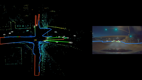
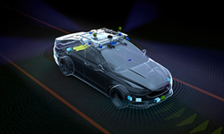
The ability to detect and react to objects all around the vehicle makes it possible to deliver a comfortable and safe driving experience. Self driving cars are usually equipped with a diverse set of sensors in various configurations to be capable of providing reliable surround perception. Surround camera and radar sensor setups are among primary surround perception system options in the auto industry, due to the feasibility of sourcing them at mass scale.
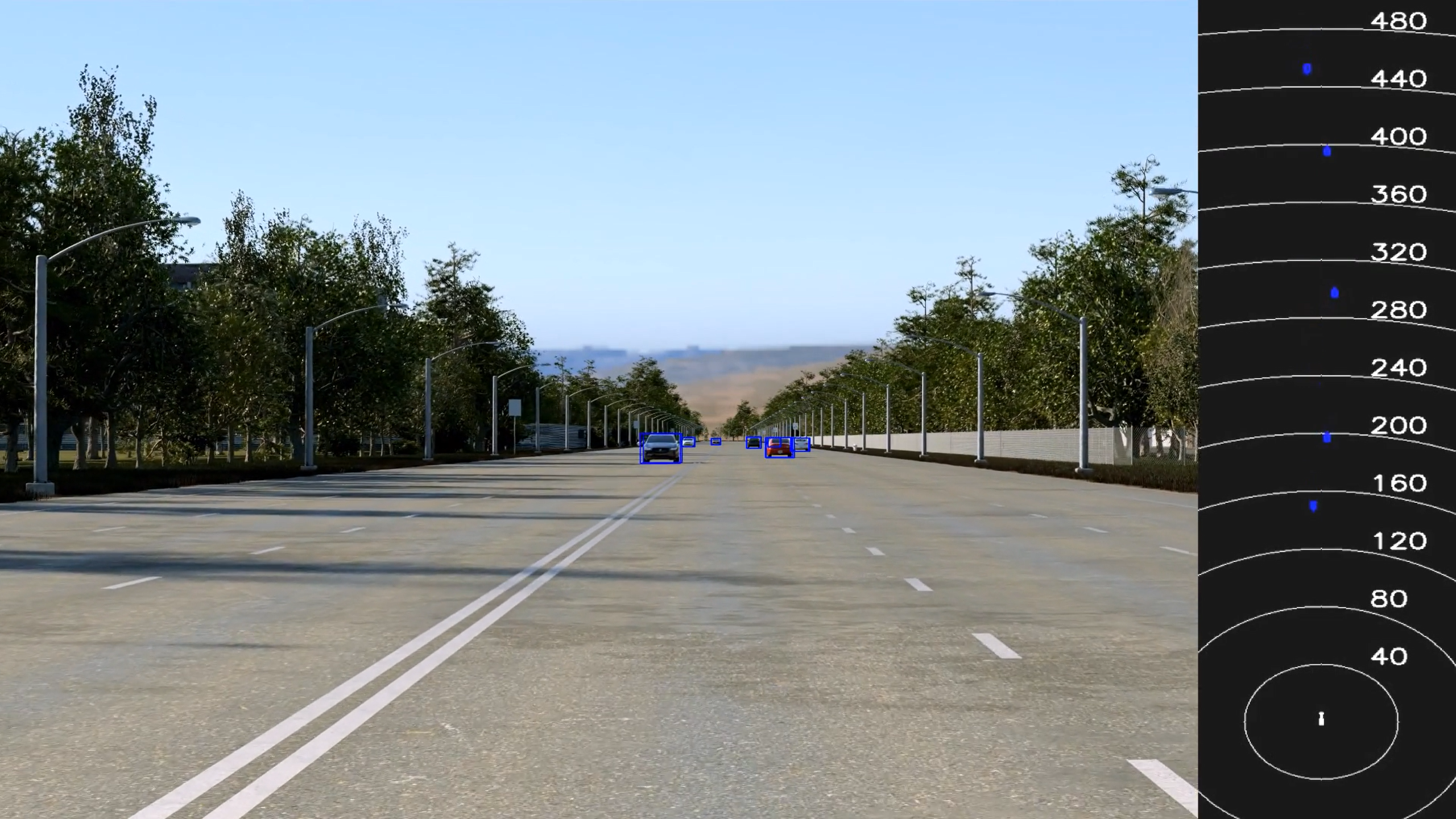
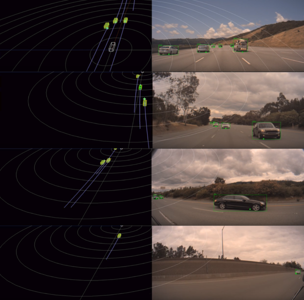
As useful as these sensors can be individually, each sensor type has its own limitations. Camera data can provide a semantic representation of the scene, but it’s inherently weak with 3D information. Radar data, on the other hand, delivers good distance and velocity estimation for obstacles, but lacks in semantic representation. In this DRIVE Labs video, we explain why it is essential to have a sensor fusion pipeline which can combine these two types of perception signals from both sensor types to provide robust surround perception.
Surround camera-radar fusion is a sensor fusion layer built on top of surround camera and surround radar perception pipelines. It is designed to leverage the complementary strengths of each sensor type and provide quality semantic information as well as accurate position, velocity and acceleration estimates. The core camera-radar fusion functions are re-used for each camera, such that the overall pipeline is easily scalable .
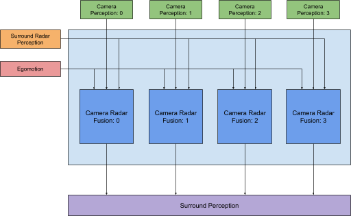
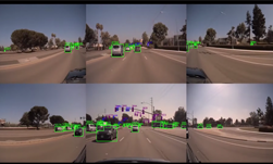
Figure 1. Surround camera-radar fusion processing pipeline in a 4-camera, 8-radar sensor configuration.
Camera Radar Fusion
The camera-radar fusion module is the main building block of the surround camera-radar fusion pipeline (Figure 1). It fuses objects generated from a single camera with objects from surround radar perception. The core idea behind this is an effective method to match objects across the sensors and combine their perception signals in a way that improves the quality of 3D information generated about the object.
Preprocessing
Preprocessing is necessary to identify the right set of camera objects and radar objects for the matching (i.e. fusion) process. This can be achieved using a simple technique such as considering the objects which fall in the intersection of the fields of view of camera and radar perception This approach is quite effective in filtering out irrelevant objects that appear in the general scene.
In this step, we also update object data to aid in the fusion process. It is especially important in this context that camera and radar perception pipelines each run on individual threads. Moreover, camera perception typically generates object measurements at different update frequencies compared with radar perception. In fact, more often than not, the camera perception update frequency is higher than that of radar. For this reason, it is essential to bring objects from both the sensors into a common update frequency in order to correctly fuse the measurements.
Object Fusion
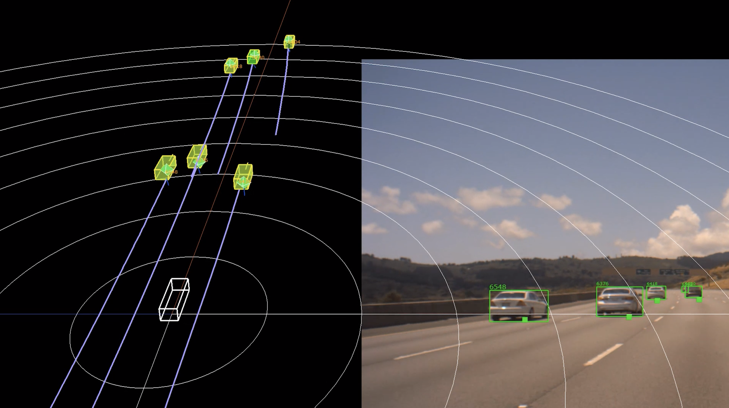
Fusion process begins with object matching or association across both the sensors. It is essentially a bipartite matching problem. For every object generated from camera perception we would like to find its corresponding object from radar perception and vice versa.
Coming up with a heuristic or a cost metric to determine potential matches is the most important aspect of this step in the fusion pipeline. The cost metric is designed in a data-driven manner by analyzing the behavior of individual perception signals from both the sensors. It accounts for how signals such as position, velocity, time-to-collision and azimuth of objects from different sensors compare against each other. It also considers how well the objects match temporally over their detection history.
This cost metric is applied across all the object pairs from both sensor types. The objects corresponding to a pair which has the minimum cost among all the other pairs with at least one object in common, are determined as matches. Once the objects are matched, perception signals are fused by using uncertainty estimates to generate reliable 3D signals for downstream planning and control modules.
Surround Camera Radar Fusion is flexible, supporting a wide variety of sensor configurations, including 6-camera, 8-radar; 4-camera, 8-radar; 2-camera, 4-radar; 1-camera, 1-radar; etc.